Shaft Alignment Math
link to : math | math graphics | outline
|
Peterson Alignment kits utilize
the rim-and-face method of shaft alignment. A general description
of the procedure follows.  Model #30RA in place Vertical Plane VF=(R180-R0)/2 + E(F180-F0/H) (N stands for near, F stands for far) The first portion, [ (R180-R0)/2 ] is the misalignment measured from the radial dial indictor (and is the same in both equations). The actual number taken off of the dial indicator is twice the misalignment, as explained by the following diagram: 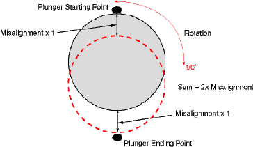
Cleaning Up HF=(R270-R90)/2 + E(F270-F90/H) (N stands for near, F stands for far) Instead of our ending values being taken from 180°, they are now taken from 270°. Instead of our ending values being taken from 0° where they were zero, they are being taken from 90°. The concept is still the same, only shifted 90°. |
Math Explanations
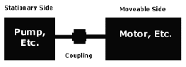 Figure 1 FIGURE 1: The stationary equipment will be to the left of the coupling. This will generally be a pump or any similar assembly which has outside connections attached to it, making it difficult or impossible to move. 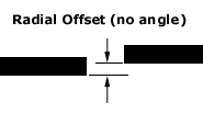 Figure 2 FIGURE 2: Radial offset is the amount of misalignment strictly from a standpoint of a height dimension. 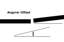 Figure 3 FIGURE 3: Angular offset is the amount of misalignment due to the perceived angle the shaft to be aligned is in relation to the stationary shaft. When the shaft has angularity, the misalignment will depend where the measurement is taken. Hence, shim requirements will be different at the front feet compared to the back feet. 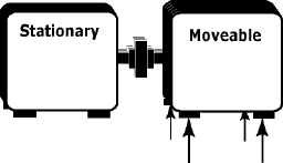 Figure 4 FIGURE 4: Front and back feet. The front feet are both motor bolts nearest the coupling assembly. Conversely, the back feet are both bolts farthest from the coupling assembly. 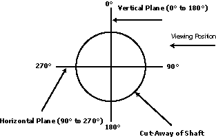 Figure 5 FIGURE 5: Vertical and horizontal plane notations. 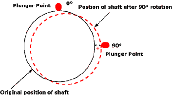 Figure 6 FIGURE 6: Rotation of the radial dial indicator and path for a positive dial movement 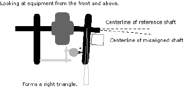 Figure 7 FIGURE 7: We see how angularity is measured.
A right triangle is formed, of which we know two of the dimensions.
(1) The dial indicator reading is the base of the triangle (Adjacent)
and is measured in thousandths. (2) The hypotenuse of the triangle
is the "swing" of the dial indicator, defined as the
diameter of the circle of revolution (see Figure
8, below), and is measured in inches. Simply put, these two
numbers allow us to figure the misalignment per inch traveled
away from the plunger point of the angular dial indicator. 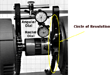 Figure 8 FIGURE 8: This picture shows the outline of the diameter of circle of revolution, or the circle the angular indicator will scribe as it is rotated about the shaft centerline. |
Alignment
Outline
|
Overview Your motivation to perform an "alignment" on your power transmission equipment may fall into one of three general categories: (1) A New Installation; (2) Re-alignment after coupling/bearing replacement; (3) Preventive maintenance. Your goal is to accurately bring equipment on one side of the coupling (say the right side) into precise alignment with equipment on the opposite side (the left side, or reference). To visualize what you need to do, imagine holding two pencil erasers (that are on the end of a new pencil) close together, but not touching each other. The reference pencil will be in your left hand, and the pencil you would like aligned with it is in your right hand. How can you accurately measure where the right hand pencil is in relation to the reference pencil on the left? That's where shaft alignment equipment comes into the picture. Preliminary Inspection If your equipment has been previously installed and is displaying obvious warning signs that something is wrong, such as excessive heat or vibration, or you've performed more than one replacement on this particular equipment, misalignment is definitely a candidate as the culprit. There could be more too it than that, however, and it's a good idea to check for what's known as "Soft Foot". Soft foot is the term commonly applied to that condition which exists when all four (4) of the machine feet are not supporting the weight of the machine. This condition is one of the major causes of frustration and lost productivity. First Step Careful measurements and technique play a critical role when preparing to do an alignment. Reference points and dial indicator readings are all part of package. Once you are ready to perform the alignment procedure, as many as five (5) physical measurements must be taken from the equipment. This includes the (1) SWING DIAMETER, the distance to the (2) FRONT and (3) BACK feet of the moveable machine (to the right of the coupling), and the distance to the (4) FRONT and (5) BACK feet of the stationary machine (to the left of the coupling). These measurements are generally done with a tape measure. Although you should be as accurate as possible when measuring from stated reference points, these initial physical measurements are not as critical as the dial indicator readings themselves. Second Step Once the initial physical measurements are taken and the alignment equipment is mounted and secured, you are then ready to "rotate" the alignment equipment on the shaft and coupling assembly. By doing this, you will obtain the three pairs of dial indicator numbers, which then describe the position of the moveable side of the coupling with respect to the stationary (or "reference") side. Last Steps Involved Once the physical dimensions and the dial indicator readings are collected, the last step is to plug these numbers into the formulae provided to determine the shims needed in the vertical direction, and any adjustment from side-to-side in the horizontal direction. Summary It is rare that your equipment will be in precise alignment after shimming for the first time. It may take at least two or three times to bring your equipment into alignment within an accepted tolerance range. With the right maintenance equipment and a positive mental attitude, shaft alignment doesn't need to invoke the terror and agony once associated with the process. |